OpenCPI Kernel Driver Functionality Guide
OpenCPI Kernel Driver Functionality Guide
References
The documents listed in the following table are referenced within the document.
Title |
Published By |
Link |
OpenCPI Component Development Guide |
||
OpenCPI Ethernet Transport Performance Tuning Guide |
||
OpenCPI User Guide |
Overview
Open-Source Component Portability Infrastructure (OpenCPI) is a development and runtime framework that exposes component-based development (CBD) for heterogeneous embedded computing environments. This is often used for the development of Software Defined Radio (SDR) applications. This document assumes some familiarity with OpenCPI, however aspects which are significant to this document are introduced and explained to allow this document to be read alone.
Components, also known as workers, are controlled by control software; refer to the OpenCPI Component Development Guide for further information. The Control Plane (CP) refers to the infrastructure to support control software and to allow it to communicate with workers. Workers exchange data via the Scalable Data Plane (SDP). Given the heterogeneous nature of the target platforms the CP and SDP are required to run over many diverse physical and transport layers such as AXI, PCI Express, Ethernet, etc.
One of the primary targets for OpenCPI is Linux based embedded platforms. A large degree of platform functionality is implemented within the Linux Kernel through the use of an OpenCPI kernel mode driver. This driver resides within the source tree in os/linux/driver/opencpi.c. This is used in conjunction with a considerable amount of userspace code that reside in the runtime directory of the source tree.
The kernel driver is a large driver that implements interfaces for the CP, SDP & FPGA bitstream loading. This driver is the focus of this document. This document is targeted at engineers wishing to extend the driver to support additional platforms.
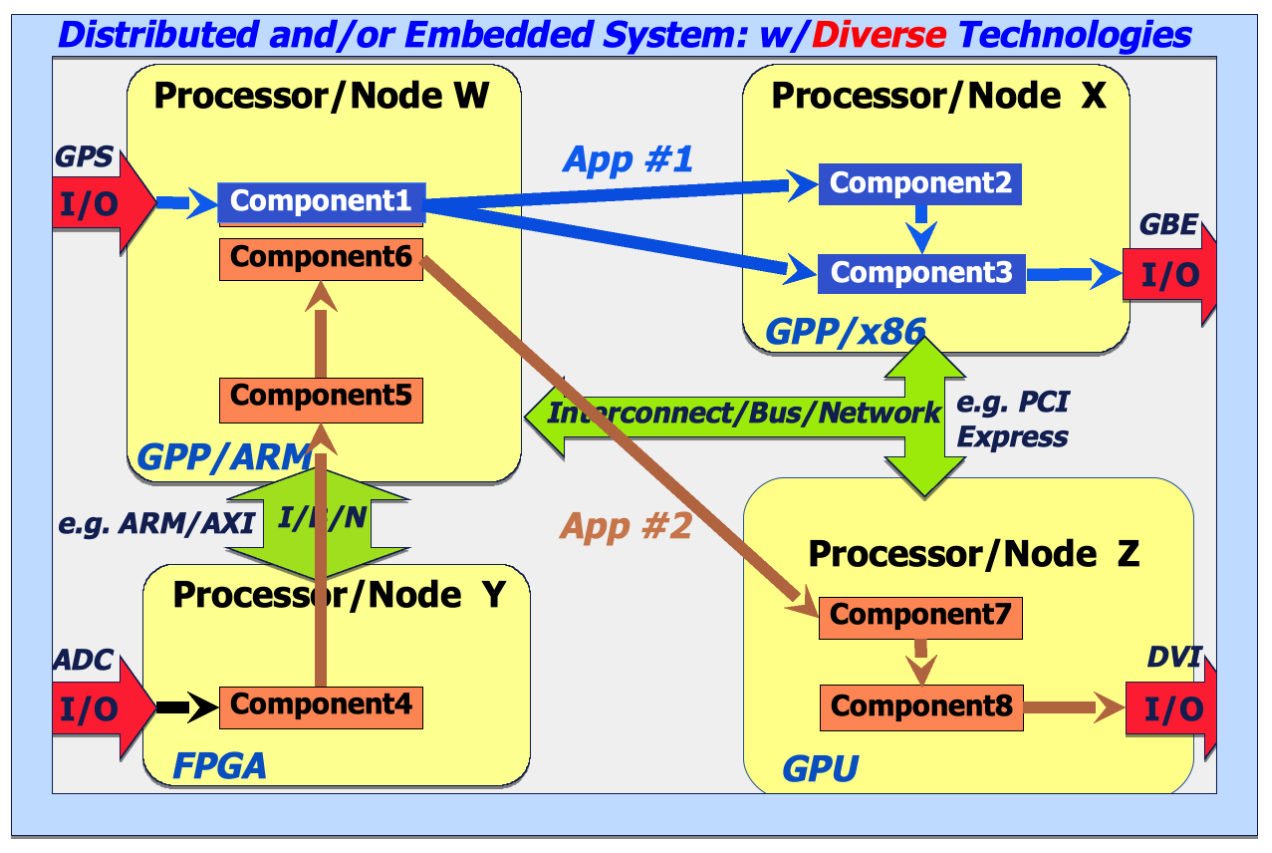
Figure 103: Embedded System with Diverse Processing and Interconnect Technologies
Technology Considerations
As mentioned, OpenCPI supports operation over various physical and transport layers. The OpenCPI kernel driver contains code which specifically handles support for interfaces on particular technologies. Considerations for these technologies is discussed below.
Xilinx System on Chip Environments
The Xilinx Zynq and Ultrascale+ platforms are System on Chip (SoC) devices featuring an embedded ARM processor and Field Programmable Gate Array (FPGA) on the same die. These are capable devices that usually run a Linux based operating system. OpenCPI workers may either be implemented in the Programmable Logic (PL) or within the Processing System (PS). Control software will usually reside within the PS. The Control Plane and Data Plane operate over the system AXI buses.
Bus Selection
The AXI buses used depend on the purpose.
Control Plane
The OpenCPI control plane is used to perform software configuration of workers; this places the following requirements on the bus used to perform this operation:
Processing System is the bus master
Access must be uncached without an explicit flush operation
Data rate is not a priority for this interface as only command and control traffic must flow over it.
The buses selected for this purpose are:
Device |
Bus |
Physical Address |
Comment |
Zynq-7000 |
AXI_GP0 |
0x40000000 |
Used in preference over GP1 |
Zynq-7000 |
AXI_GP1 |
0x80000000 |
Used if GP0 already reserved |
Ultrascale+ |
M_AXI_HPM0_FPD |
0xA8000000 |
Note the non-zero offset from the base address of 0xA0000000 for HPM0 |
The bus selection is hard-coded within static int __init opencpi_init(void). This definition must match that within runtime/hdl/include/HdlZynq.hh and runtime/hdl/src/HdlBusDriver.cc which is the corresponding userspace request. See Userspace Device Handles section for more information.
Scalable Data Plane
The purpose of the SDP on Xilinx devices is to move data to/from workers implemented in the PL and workers in the PS. This is achieved by moving data in blocks, the data to be moved is placed in DRAM at a known address then the data is accessed via one or more dedicated AXI buses. The selection of these buses are determined by the “platform worker”. The buses typically selected for this purpose are:
Device |
Bus |
Comment |
Zynq-7000 |
AXI_HP{3:0} |
It is not possible run all buses at full data rate due to bottlenecks later in the data path. |
Ultrascale+ |
S_AXI_HP{3:0}_FPD |
The data paths are shared with other device features, for example S_AXI_HP0_FPD shares a data path with the DisplayPort data bus. |
PCI Devices
When compiled with CONFIG_PCI the OpenCPI device driver registers itself as a PCI Driver. This allows the driver to probe for OpenCPI PCI devices. This is achieved by opening candidate PCI devices and attempting to read the 64bit magic word (“OpenCPI”) from the PCI address space. On a successful probe the driver creates a device handle and maintains an open IO mapping for later memory mapping operations from IOCTL calls on this device.
The driver creates a series of device handles for userspace access. These are named uniquely based upon the devices PCI domain, bus number, slot and function. The naming scheme is detailed in Table 93:.
Bus Selection
When the PCI device is registered the driver will attempt to register the start of the memory spaces on both Base Address Register (BAR) 0 and BAR 1. These addresses are then presented as two adjacent memory mappings via an mmap on the major 0 device (see Userspace Device Handles section). The OpenCPI userspace device uses these mappings during its control plane and DMA access operations.
Bus |
BAR |
Offset on bus |
Control |
0 |
0x0 |
Data |
1 |
0x0 |
Ethernet Devices
OpenCPI supports devices connected over an Ethernet interface. The Linux kernel driver registers additional networking domain, also known as protocol family 12, or “PF_OPENCPI”. Under this protocol family a further three ethertypes are registered, as shown in Table 92:, representing the control and dataplane packet types. The accompanying OpenCPI runtime code ultimately abstracts this interface and presents the control plane and data plane as a standard OpenCPI transport layer.
Type |
Value |
Purpose |
OCCP_ETHER_MTYPE |
0xF040 |
Control plane access |
OCCP_ETHER_STYPE |
0xF040 |
Unused - aliases to OCCP_ETHER_MTYPE in any event |
OCDP_ETHER_TYPE |
0xF042 |
Dataplane access |
The Ethernet types here allow for separation of the data flows over Ethernet automatically by the Linux networking stack. All processing of the packet contents is performed in userspace with the kernel driver simply passing data to and from the networking stack.
Further details of this interface are out of scope of this document. The Ethernet Transport Performance Tuning Guide describes tuning performance over this interface, which interested parties are invited to read.
Userspace Device Handles
The OpenCPI Linux driver generates multiple userspace device interfaces. This allows the runtime code to interact with different OpenCPI devices, while enabling the driver to distinguish between calls made to each device.
OpenCPI userspace code only interacts with device handles created by udev or mdev, which are shown in Table 93:. OpenCPI includes udev and mdev rules which are used to rename devices. The rules are necessary to overcome limitations in the device names that may passed to device_create. The rules include support for devices which are not created by the kernel driver, these are shown in Table 94:. A complete list of all sysfs device handles created by the kernel driver is documented in Table 95:
Device |
Purpose |
/dev/ocpi=mem |
Main device handle, used for memory reservations, FPGA loading etc |
/dev/ocpi/mem |
Symlink to /dev/ocpi=mem |
/dev/char/ocpi=mem |
Symlink to /dev/ocpi=mem |
/dev/ocpi=pci=A:B:C.D |
PCI device handle Where: A: PCI Domain Number B: PCI Bus Number C: PCI Slot D: PCI Function |
/dev/ocpi/pci/A:B:C.D |
Symlink to /dev/ocpi=pci=A:B:C.D |
The device /dev/ocpi=pci is created as /dev/ocpi=p. This is renamed by udev or mdev to the form in Table 93:
Device |
Purpose |
/dev/ocpi=ether=AA:BB:CC:DD:EE |
Remote Ethernet device handle |
/dev/ocpi/ether/AA:BB:CC:DD:EE |
Symlink to /dev/ocpi=ether=AA:BB:CC:DD:EE |
The above devices would be created by udev or mdev rules if the kernel driver created the device /dev/ocpi=e. The form of the ethernet MAC address would be updated from the form AABBCCDDEEFF to the standard form AA:BB:CC:DD:EE. The driver contains evidence of additional unimplemented functionality related to Ethernet interfaces in the OCPI_CMD_DISCOVER section.
Device |
Purpose |
/sys/kernel/debug/printk/index/opencpi |
Debug print control |
/sys/bus/pci/drivers/opencpi/bind |
Handle for binding the driver to a PCI device. |
/sys/bus/pci/drivers/opencpi/module |
Symlink to /sys/module/opencpi |
/sys/bus/pci/drivers/opencpi/new_id |
Handle for adding a new device ID |
/sys/bus/pci/drivers/opencpi/remove_id |
Handle for removing a device ID which was created using new_id |
/sys/bus/pci/drivers/opencpi/uevent |
Sysfs entry for generating udev uevents |
/sys/bus/pci/drivers/opencpi/ubind |
Handle for unbinding the driver from a PCI device |
/sys/class/opencpi/ocpi=mem |
Symlink to /sys/devices/virtual/opencpi/ocpi=mem |
/sys/module/opencpi/drivers/pci:opencpi |
Symlink to /sys/bus/pci/drivers/opencpi |
/sys/devices/virtual/opencpi/ocpi=mem/ dev |
Main device handle. Sysfs entry corresponding to /dev /ocpi=mem |
/sys/devices/virtual/opencpi/ocpi=mem/ power/autosuspend_delay_ms
/sys/devices/virtual/opencpi/ocpi=mem/ power/control
/sys/devices/virtual/opencpi/ocpi=mem/ power/runtime_active_status
/sys/devices/virtual/opencpi/ocpi=mem/ power/runtime_status
/sys/devices/virtual/opencpi/ocpi=mem/ power/runtime_suspended_time
|
Power management control, only present when CONFIG_PM=y Feature not used. |
/sys/devices/virtual/opencpi/ocpi=mem/ subsystem |
Symlink to /sys/class/opencpi |
/sys/devices/virtual/opencpi/ocpi=mem/ uevent |
Sysfs entry for generating udev uevents |
/sys/module/opencpi
/sys/module/opencpi/initsize
/sys/module/opencpi/uevent
/sys/module/opencpi/notes
/sys/module/opencpi/notes/.note.Linux
/sys/module/opencpi/notes/.note.gnu.build-id
/sys/module/opencpi/notes/ .note.gnu.property
/sys/module/opencpi/taint
/sys/module/opencpi/holders
/sys/module/opencpi/refcnt
/sys/module/opencpi/coresize
/sys/module/opencpi/initstate
/sys/module/opencpi/sections
/sys/module/opencpi/sections/__param
/sys/module/opencpi/sections/.plt
/sys/module/opencpi/sections/.text.ftrace_trampoline
/sys/module/opencpi/sections/.note.Linux
/sys/module/opencpi/sections/.strtab
/sys/module/opencpi/sections/.exit.text
/sys/module/opencpi/sections/.bss
/sys/module/opencpi/sections/.gnu.linkonce.this_module
/sys/module/opencpi/sections/.symtab
/sys/module/opencpi/sections/.rodata
/sys/module/opencpi/sections/.init.text
/sys/module/opencpi/sections/.note.gnu.build-id
/sys/module/opencpi/sections/.text
/sys/module/opencpi/sections/.init.plt
/sys/module/opencpi/sections/.data
/sys/module/opencpi/sections/.rodata.str
/sys/module/opencpi/sections/__bug_table
/sys/module/opencpi/sections/.text.unlikely
/sys/module/opencpi/sections/.note.gnu.property
/sys/module/opencpi/sections/.rodata.str1.8
|
Standard sysfs module parameters |
Available File Operations
The following operations are available on the OpenCPI device handles.
Operation |
Purpose |
open |
Debug logging of file and i_node information. For PCI devices the apparent file size is also updated to be equal to the sum of the BAR0 and BAR1 mapped region sizes. This value is unused elsewhere however. |
release |
Release memory reservations when releasing minor 0 |
ioctl |
Main interface for performing IO operations |
mmap |
Memory mapping, used for register access & DMA data access. Caching is controlled via use of O_SYNC. |
Driver IOCTL Calls
Through IOCTL calls, applications can perform specialized input/output operations on OpenCPI’s userspace device handles. These operations include tasks such as memory reservation and FPGA bitstream loading. The individual IOCTL commands are detailed below.
OCPI_CMD_STATUS
This IOCTL is used to report on the memory allocations and reservations performed by the driver.
I/O data
ocpi_status_t - see OsKernelDriver.h for struct definition.
The struct consists of three fields:
allocated: Total memory allocated by the driver.
available: Memory available to the mapped.
largest: Largest memory block available.
These values are all populated during the IOCTL call.
Error codes
EFAULT: Error in copying result to user, e.g. insufficient buffer supplied to IOCTL call.
OCPI_CMD_REQUEST
Request a memory reservation.
I/O data
ocpi_request_t - see OsKernelDriver.h for struct definition.
The struct consists of the following fields:
needed: How much memory is needed by this request.
actual: How much memory you will receive.
address: Physical address of the data block from the point of view of the processor.
bus_addr: The address usable from another bus master to see this DMA memory.
how_cached: Obsolete, maintained for compatibility.
The input data is updated with actual, address and bus_addr fields updated based upon the reservation before being returned to the user, all other fields are unaltered.
Error codes
EFAULT: Error in copying data to or from the user, e.g. insufficient buffer supplied to IOCTL call.
ENOMEM: Failure to allocate memory. Details on the failure will be available in the kernel logs.
OCPI_CMD_PCI
Retrieve PCI device address range. This is a read-only IOCTL call and is immediately called by the runtime code when opening a PCI device.
I/O Data
ocpi_pci_t - see OsKernelDriver.h for struct definition.
The struct consists of the following fields:
bar0: Address of the BAR0 memory region mapping.
bar1: Address of the BAR1 memory region mapping.
size0: Size of the region of BAR0 reserved.
size1: Size of the region of BAR1 reserved.
Error codes
EFAULT: Error in copying data to or from the user, e.g. insufficient buffer supplied to IOCTL call.
EINVAL: This IOCTL is called on a non-PCI device.
OCPI_CMD_DISCOVER
This command is intended for using with discovery of Ethernet endpoints but is unimplemented.
OCPI_CMD_LOAD_FPGA
Load bitstream via FPGA Manager framework. This will first copy the raw bitstream into kernel memory before requesting the FPGA be loaded via the FPGA Manager Framework. It should be noted that the bitstream will be passed for loading directly and must therefore not include any additional framing beyond that provided by Vivado.
I/O Data
ocpi_load_fpga_request_t - see OsKernelDriver.h for struct definition.
The struct consists of the following fields:
data: Userspace pointer to the bitstream to be loaded.
length: The size in bytes of the bitstream pointed to by data.
device_path: The path to the FPGA device manager. This can vary by platform, for example for an Ultrascale+ device this is “/firmware/zynqmp-firmware/pcap”. Note there is a 100 character limit on this path, this includes the null terminator.
Error codes
EFAULT: Error in copying data to or from the user, e.g. insufficient buffer supplied to IOCTL call.
EBUSY: FPGA could not be locked for programming.
EFAULT: Error during loading.
ENOMEM: Unable to allocate sufficient kernel memory for bitstream.
ENOENT: Unable to locate FPGA Manager.
In all error cases additional information is available via the kernel logs.
OCPI_CMD_INVALIDATE
Synchronize memory region for CPU access.
I/O Data
ocpi_cache_t - see OsKernelDriver.h for struct definition.
The struct consists of the following fields:
address: Bus address for cache operation.
size: Size of region to operate on in bytes.
Error codes
EFAULT: Error in copying data to or from the user, e.g. insufficient buffer supplied to IOCTL call.
OCPI_CMD_ FLUSH
Synchronize memory region for device access.
I/O Data
ocpi_cache_t - see OsKernelDriver.h for struct definition.
The struct consists of the following fields:
address: Bus address for cache operation.
size: Size of region to operate on in bytes.
Error codes
EFAULT: Error in copying data to or from the user, e.g. insufficient buffer supplied to IOCTL call.
Control Plane Access
The OpenCPI control plane conceptually spans all parts of a heterogeneous target environment, i.e. CPUs and FPGAs. Much of the support for the control plane is abstracted within OpenCPI code, providing users with a uniform interface for controlling workers. Aspects of control plane access is summarized here to aid understanding.
The control plane is accessed from userspace via memory mapping of the bus which connects the CPU and FPGA.
Xilinx SoC devices
In the case of a Xilinx SoC, access to the control bus is via AXI transactions which are sent over the appropriate bus, as shown in Table 89:. Corresponding HDL infrastructure code within OpenCPI then converts these into control plane operations and delivers them to the HDL worker.
Access to the AXI is achieved through opening and mmaping /dev/mem, a generic memory mapping kernel interface, using the physical address of the AXI bus. This operation requires root access due to the wide range of access this device provides.
PCI devices
Memory access for the PCI devices is provided through the appropriate OpenCPI character device handle - /dev/ocpi/pci/A:B:C.D. This is because a /dev/mem handle is not generally guaranteed to exist on any given target system and the physical addresses required are best determined by the device driver. Instead performing mmap on the appropriate PCI OpenCPI device will return a direct mapping to either the reserved BAR0 or BAR1 memory regions based upon the supplied start address, i.e.:
Start Address |
Returned mapping |
0 |
BAR0 |
BAR0 size |
BAR1 |
Attempting to map any other size other than the full OpenCPI control plane size will return an EINVAL error.
Ethernet devices
Ethernet device control plane access is fully provided in userspace with the OpenCPI Linux driver providing the control and dataplane ethertypes only, as shown in Table 92:. Instead the userspace control plane accessor is set to be an instance of the OCPI::HDL::Net::Device class and all operations are handled within the userspace runtime code.
DMA Operation
The following section describes DMA within OpenCPI, focussing on interactions with the Linux kernel driver.
Overview
OpenCPI requires DMA memory resources when communicating across system buses or fabrics with other platforms. This memory must be:
Accessible to the CPU (via local mmap calls)
Available to OpenCPI’s DMA engines for direct FPGA read/write access
Physically contiguous
Data transfer begins with OpenCPI DMA transport layer code using the kernel driver to ensure memory is allocated for the transfer and updating HDL infrastructure code. Using the FPGA to CPU direction as an example, during the update loop, i.e. when data is being transferred, when an RCC worker downstream signals it’s ready to receive data from an HDL worker upstream. This signal releases the HDL’s flow control constraints, allowing the HDL worker to transmit data through the SDP into the pre-allocated memory spaces. Once the data transfer completes, the system flags the RCC worker and uses the kernel driver to flush the memory region. This flushing step clears the CPU cache-lines before the RCC worker reads the transferred data. Simplified DMA transfer process PL to PS and Simplified DMA transfer process PS to PL illustrate this sequence of events in a simplified format.
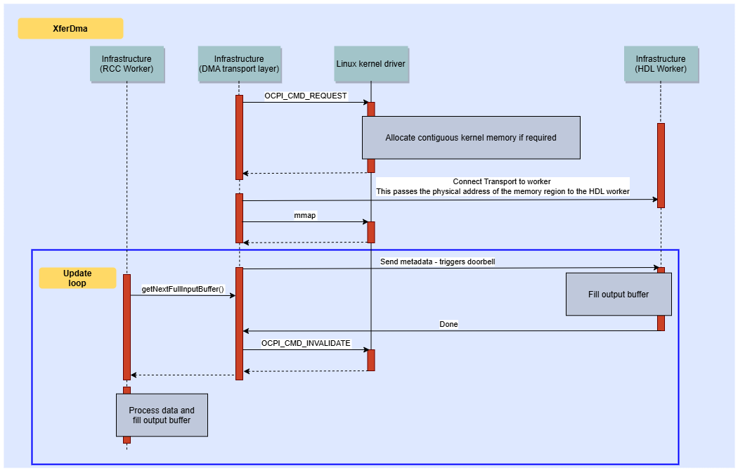
Figure 104: Simplified DMA transfer process PL to PS
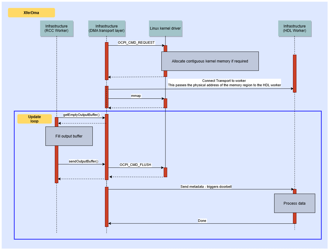
Figure 105: Simplified DMA transfer process PS to PL
DMA transfers
Flow control modes
The HDL defines three possible port modes for OpenCPI DMA, they are as follows:
Passive: There are no flow control messages. This relies upon the other end of the transfer to indicate the state and buffer usage.
ActiveMessage: The port will move the data, for a producer this means pushing data to the consumer, for a consumer this means pulling data from the producer.
ActiveFlowControl: The port will not move the data but instead will provide active feedback. For a producer this means telling the consumer when buffers are available to read from. For a consumer this means telling the producer when the buffers are available to fill.
Passive is rarely, if ever, used and will not be discussed further in this document.
In both transfer directions the HDL component takes on the role of ActiveMessage for Xilinx devices, this is not necessarily the case for other platforms. In this mode the HDL is responsible for the movement of data, this bypasses the involvement of the CPU for bulk data transfer. Flow control is provided through the use of “doorbell” signals. For PS to PL transfers the doorbell signal indicates that a read request is available for the HDL to process and start a read transfer. For PL to PS transfers the doorbell signal indicates that write request is ready and there is an available buffer to write data into.
The same property is used in both scenarios - “remote_doorbell”, which is defined in sdp-properties.xml. This signal becomes memory mapped within the OpenCPI runtime transport descriptor as fullFlagBaseAddr for PS to PL transfers or emptyFlagBaseAddr for PL to PS transfers. The HDL uses the “remote_doorbell_any_written” signal as a write enable on the metadata FIFO to clock a new metadata work into the FIFO which is then read out into the SDP clock domain and processed by the SDP state machine.
The other properties within sdp-properties.xml are encoded into a metadata word. These provide information on the buffer physical address, length, and so on.
PL to PS Transfers
When transferring data from the Programmable Logic (PL) to the Processing System (PS), the DMA state machine writes data from the Block RAM (BRAM) to the location specified in the metadata provided on the Control Plane. After completing this transfer, the HDL worker signals completion which is detected as a full buffer in the PS and depending on the cache mode, the driver may need to flush the cache memory. At this point, the PS can read and process the data. This sequence can then repeat for subsequent data buffers.
5.2.3 PS to PL Transfers
PS to PL transfers occur in a similar fashion to PL to PS transfers. The remote_doorbell property instead indicates the presence of data that is available to read. The metadata encodes the information regarding the size and location of the DRAM buffer as before. The data is pulled from the DRAM and written to a Block RAM (BRAM) for downstream consumption.
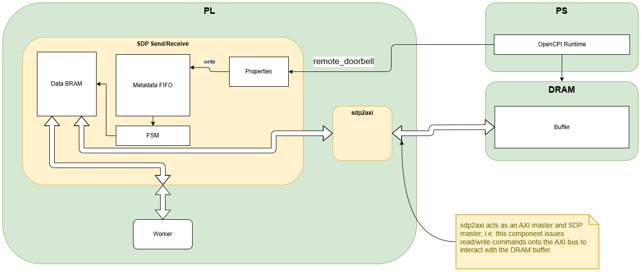
Figure 106: Xilinx SoC DMA
5.3 DMA buffer allocation
The DMA process can involve multiple separate buffers and this is split between BRAM memory allocated on the FPGA and DRAM memory allocated by the processing system.
The SDP Send and SDP Receive components allocate a Block RAM (BRAM) backed memory block. The total amount of FPGA provisioned memory is determined by the “memory_bytes” property of sdp-properties.xml. This is subdivided into a number of logical buffers, each of size “buffer_size”. The total amount of buffering is limited by the amount of BRAM resource within the FPGA.
On the PS side a single large DRAM buffer is allocated on start-up, by default 128 KB. The driver will then assign memory blocks within this pool.
When a DMA transfer occurs it is between the BRAM memory and the DRAM that the transfers occurs with the PL acting as an AXI bus master and issuing read or write commands to the DRAM controller based upon the addresses that have been passed to it via the metadata word provided on the control plane.
The amount of buffering is fixed at runtime and does not increase based upon backpressure. The amount of memory allocated by the runtime can be configured via the “buffersize” and “buffercount” attribute of each Connection within an application. This is specified within the application XML definition.
The process is represented pictorially in SDP Send Process and SDP Receive Process.
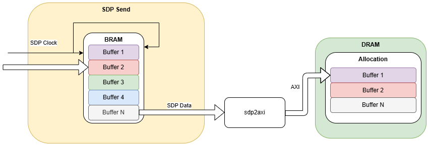
Figure 107: SDP Send Process
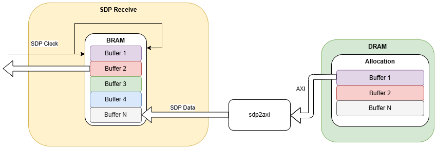
Figure 108: SDP Receive Process
The decision on the appropriate values for buffer_size and memory_bytes will be determined by the following factors:
How much BRAM resource is present on the target device.
How many concurrent endpoints are expected to be used - ideally allocate at least as many buffer regions as endpoints to allow for independent flow control.
The minimum amount of data that must be transferred without providing back-pressure.
The expected message size through the application.
It should be noted that memory_bytes is currently a hard coded value within sdp-properties.xml and is not intended to be modified by the user, as of OpenCPI v2.4.7.
The SDP Send & Receive will use each of the buffer blocks within the BRAM in a round-robin fashion, that is, a single HDL worker may fill multiple buffer elements before backpressure is applied. A single message however must fit within a buffer and a buffer only ever contains a single message. The DRAM buffer may be larger and may be filled with multiple messages. The buffer size is set by the runtime at endpoint creation during application start and is typically handled automatically by OpenCPI, based on the OpenCPI protocols used by the ports in a connection, however can be controlled by the “buffersize” and “buffercount” attributes of the application XML. This is important if the ports within a connection do not use an OpenCPI protocol.
Increasing the amount of PL buffering will not necessarily improve the DMA performance. The rate-limiting step for continuous DMA will relate to the time taken to process the data in userspace and re-post the buffer via the metadata FIFO. Increasing the amount of PL-side buffering will help deal with jitter in the processing time on the processor side but cannot help if the software processing is not sufficient on average. Therefore it is expected that for the majority of use cases it is sufficient to allocate two buffers per endpoint. This allows for the downstream component to continue sending or receiving whilst software is preparing the next buffer.
The logic for adjusting the amount of buffering on the PS is similar to that of the PL side, increasing the buffer count above two is unlikely to provide much benefit beyond increased protection from processing time jitter. Increasing the buffer size will decrease the amount of time spent in overhead logic, as this duration is fixed for any given buffer, independent of the buffer size. However, a large buffer will result in increased latency as processing of the buffer cannot begin until the buffer has been filled.
Default Allocation
By default, the OpenCPI kernel driver allocates 128 KB for its Linux kernel device driver via the DMA API. If the DMA API allocation fails, it will try to request kernel pages instead, ensuring at least 16 KB is allocated. Applications may require additional DMA memory depending on their buffering needs. The application will issue an IOCTL call for all required DMA memory on start-up based upon the endpoint requirements as defined by the shared memory buffer size, which can be controlled via the OCPI_SMB_SIZE environment variable and “smbsize” element within the platform system configuration file, as defined in the OpenCPI User Guide. This may cause additional allocations to occur if there is insufficient reserved memory. This memory will be retained until the driver is unloaded.
The OpenCPI kernel driver supports allocating memory on request. Memory allocations performed on request can be up to 1024 KB.
Memory Reservation Requirements
The need to reserve DMA memory at boot time depends on two factors:
The total DMA memory required by your applications
The Linux system’s capabilities for dynamic DMA memory allocation
Some Linux systems support dynamic DMA memory allocation during runtime, while others require boot-time reservation, for modern kernels is it expected that dynamic allocation via the DMA API should be sufficient and successful in the majority of use cases. For systems requiring boot-time reservation, you must allocate sufficient memory to support your application needs.
Reserving Additional Memory
Dynamic reservation
Additional memory blocks of up to 1024 KB may be dynamically requested via the OCPI_CMD_REQUEST IOCTL system call.
This call will first attempt to assign a previously allocated block of memory to the caller. Failing this it will attempt to allocate memory using the following methods:
DMA API
Allocation of kernel memory
In the majority of cases it is expected that the DMA API will be able to successfully allocate the additional memory required for DMA. This memory will be appended to the driver’s internal memory allocation list (block_list).
Boot-time allocation for PCI Express
To reserve additional DMA block memory at boot time for PCI Express-based systems, use the Linux kernel ` memmap` parameter in the following format:
memmap=size$start
Where:
size: Amount of memory to reserve (in decimal or hexadecimal bytes)
start: Physical start address (in hexadecimal bytes)
Both values must align to 4096-byte (0x1000) boundaries
Note: this parameter is only applicable for x86 PCI Express based systems.
Memory Address Considerations
The OpenCPI PCI DMA engine requires the user-accessible DMA memory pool to be within a 32 or 64-bit memory range. Due to Linux memory management, it’s recommended to place the start address above the first 24 bits of address space.
Cache Coherency
The OpenCPI Linux driver lets the userspace runtime make decisions about caching for buses and memory regions. When a userspace device is opened with synchronous flags, the driver maps the memory as uncached. This is particularly important for the Zynq and Ultrascale+ family, where it prevents these behaviors:
Access aggregation
Reordering
Early write acknowledgement
These restrictions make the memory access suitable for direct register access. The driver implements this through this code:
if (file->f_flags & (O_SYNC|O_DSYNC))
   vma->vm_page_prot = pgprot_noncached(vma->vm_page_prot);
The OpenCPI userspace runtime controls memory access caching by using the O_SYNC flag when opening the kernel device driver handle. Users can modify this behavior by setting the OCPI_DMA_CACHE_MODE environmental variable.
Value |
Meaning |
0 - default for Ultrascale+ |
CPU caching is disabled and DMA buffer access is Synchronized. |
1 - default for other platforms |
In this mode, DMA buffers use normal caching when accessed by the CPU and the caching of a buffer’s contents is explicitly invalidated when new buffers are received by the CPU and explicitly flushed after new buffers are filled (written) by the CPU. |
2 |
This mode support cache-coherent DMA. Explicit DMA flushes are avoided and the CPU caching is enabled. Only use this mode on platforms with cache-coherent DMA. |
Releasing DMA memory
DMA memory is typically held for the duration of an OpenCPI application. Any dynamically allocated memory is released when /dev/ocpi/mem is closed at application exit. This is to allow for memory reuse and minimize DMA memory allocations which may fail.
All allocated and reserved memory is also released during driver unload, which may be triggered using rmmod.
FPGA Bitstream Loading
Bitstream loading is achieved through the use of the FPGA Manager framework.
This is achieved through the OCPI_CMD_LOAD_FPGA IOCTL command. The loading process is as follows:
Get access to FPGA manager
Allocate kernel memory to hold the bitstream. It should be noted that this operation may fail under high memory fragmentation. If this occurs then a reboot may be necessary.
Copy the bitstream from userspace to kernel space.
Pass kernel buffer to FPGA manager for loading.
Release buffer and FPGA manager.
Driver Lifecycle Summary
The following section describes the lifecycle of the driver, through load, operation and unload.
Load
Loading of the OpenCPI kernel driver is achieved through the ocpi_linux_driver script. This is responsible for parsing the opencpi_memmap and passing to the kernel module on load. If the opencpi_memmap parameter is missing it will also parse instances of memmap and, on the assumption that this mapping is intended for OpenCPI, convert it to an opencpi_memmap parameter. The script will also reload the udev/mdev rules so that they can process events after the driver is loaded.
After the OpenCPI kernel driver is loaded, it performs the following actions:
Notifies udev of the driver and registers the device creating the device handles in /dev and attributes within /sys as described above in the Userspace Device Handles section.
If the target kernel supports PCI, the driver registers itself as a PCI driver. More information can be found in the PCI Devices section.
If the target is a Xilinx Zynq architecture, it reserves memory for the GP0 or GP1 AXI interfaces (see Table 90:).
If the target is a Xilinx Zynq Ultrascale+ architecture, it reserves memory for the HP0 AXI interface (see Table 90:).
Checks for any memory that has been pre-reserved on the kernel command line, as “opencpi_memmap” and allocates that memory for use in the driver.
If no memory is pre-reserved, it allocates memory for DMA as described in the Default Allocation section.
Registers a network protocol and control plane and data plane packets (see Ethernet Devices section).
Operation
During the execution of an OpenCPI application, the kernel driver handles the userspace interactions as detailed in the Available File Operations section. Typically application execution will cause the following operations:
OCPI_CMD_LOAD_FPGA
Load FPGA bitstream
OCPI_CMD_REQUEST
Configure the transport layer code for control plane access
OCPI_CMD_REQUEST
Ensure memory is allocated for data plane DMA transfers
OCPI_CMD_FLUSH & OCPI_CMD_INVALIDATE
Synchronize CPU caches during DMA data transfers (see Cache Coherency section).
Unload
When unloaded, the OpenCPI kernel driver cleans up after itself, ensuring all memory is freed, network protocol unregistered and all devices removed.
Memory Management
Memory allocations within the OpenCPI kernel typically persist the entire time the driver is loaded, which requires the driver to store information about memory allocations. The driver refers to memory allocations as blocks and stores meta-data about blocks as they are allocated throughout its lifecycle. This meta-data includes, amongst other things, the start and end addresses, size, type and whether the memory is cached.
All blocks are maintained on a “block_list” which allows the kernel driver to:
Reuse memory whenever memory is requested by the OpenCPI transport layer code, for example when the transport layer requests memory when performing DMA transfers, this will come from the initially allocated 128 KB.
Merge adjacent memory blocks. The driver supports the merging of memory blocks into fewer, larger blocks. This can be useful on systems where the kernel driver is unable to allocate the initial 128 KB for DMA and instead received a smaller initial allocation. It is also useful to reduce memory fragmentation.
Ensure all memory allocations are freed when the driver is unloaded.
Porting Considerations
Porting this driver and userspace code to new platforms should be a largely uneventful endeavor. Points of consideration are mentioned in this section.
DMA Coherency Scheme
The standard DMA coherency arrangement is to allow the runtime code to perform explicit data synchronization, i.e. OCPI_DMA_CACHE_MODE=1, is possible as this allows the CPU to cache the data accesses in cases where the runtime knows that the HDL worker will not be writing to the data in question. If this is not possible then uncached access, i.e. OCPI_DMA_CACHE_MODE=0 provides a fallback mechanism although additional care must be taken when reading or writing to the uncached buffers so as not to incur additional overhead from the uncached accesses.
HDL Clocking Arrangement
The HDL clocking arrangement determines the ultimate rate at which registers in the control plane can be written to or read from. Similarly, for the SDP, the clock speed determines the maximum data rate at which data can be passed from an HDL worker to an RCC worker.
Linux Kernel Version
In order to build the OpenCPI Linux kernel driver, OpenCPI requires the full Linux kernel source, for the target environment, to be available at compile time. The mainline Linux kernel is maintained separately to individual Linux distributions. Individual distributions often include their own releases of the kernel, likely a specific kernel version with select patches by maintainers of that distribution. Using specific kernel versions and patches can lead to API changes in the kernel source, which may require modifications to the OpenCPI code. Ensure the exact source for the target kernel is checked, rather than assuming the mainline kernel code is the source of truth. It may also be necessary, for example to remain compatible with all versions of a Linux distribution, to determine the earliest point any changes were introduced.
As a worked example, for Rocky 9, assuming the default kernel is used
Rocky 9 ships with kernel version 5.14.
The mainline kernel for version 5.14 is here:
The exact kernel version running depends on the patch version. For example on Rocky 9.5, the kernel version is more accurately “5.14.0-503.14.1”
See the table here:
The source for “5.14.0-503.14.1” is available from the Rocky 9 repositories:
Within the mainline kernel, version 5.14, the file “skbuff.h” defines function “skb_recv_datagram”, and it expects 4 arguments:
struct sk_buff *skb_recv_datagram(struct sock *sk, unsigned flags, int noblock, int *err);
https://github.com/torvalds/linux/blob/v5.14/include/linux/skbuff.h#L3606
Looking at the code from the Rocky 9 release 5.14.0-503.14.1, the equivalent code actually expects 3 arguments and reflects a patch from mainline kernel version 5.19:
struct sk_buff *skb_recv_datagram(struct sock *sk, unsigned flags, int *err);
https://github.com/torvalds/linux/commit/f4b41f062c424209e3939a81e6da022e049a45f2
Depending on requirements, it may be acceptable to finish investigating here. However, by investigating the exact point this patch was introduced, we find it was first introduced in Rocky 8.8, kernel version “4.18.0-477.10.1”.
In order to be compatible with all Rocky 9 versions, we need to alter the kernel driver code to use the updated function prototype if we are in any Rocky 9 environment. In this example, we can in fact make this change to support Rocky 8.8 or later.