Polyphase FIR Interpolator (polyphase_interpolator)
Instead of a standard FIR interpolator, which performs upsampling first by inserting zeros and applying a low pass filter, a Polyphase FIR Interpolator has multiple branches onto which the FIR coefficients are placed. As a result the FIR calculates at the lower sampling rate and there is no requirement for inserted zeros. An output sample “switch” steps through the branches to produce the output interpolated values.
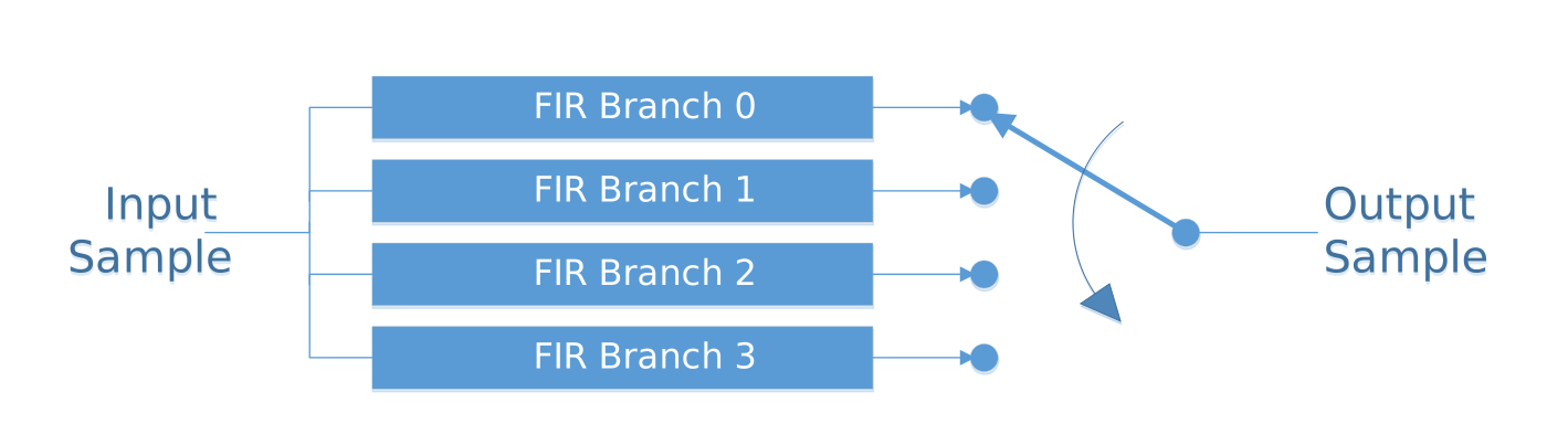
Figure 469: Output switch
An individual branch contains the structure shown below, that of a standard FIR filter, although the actual implementation uses a multiply-accumulate approach to limit the number of multipliers used to one for resource efficiency.
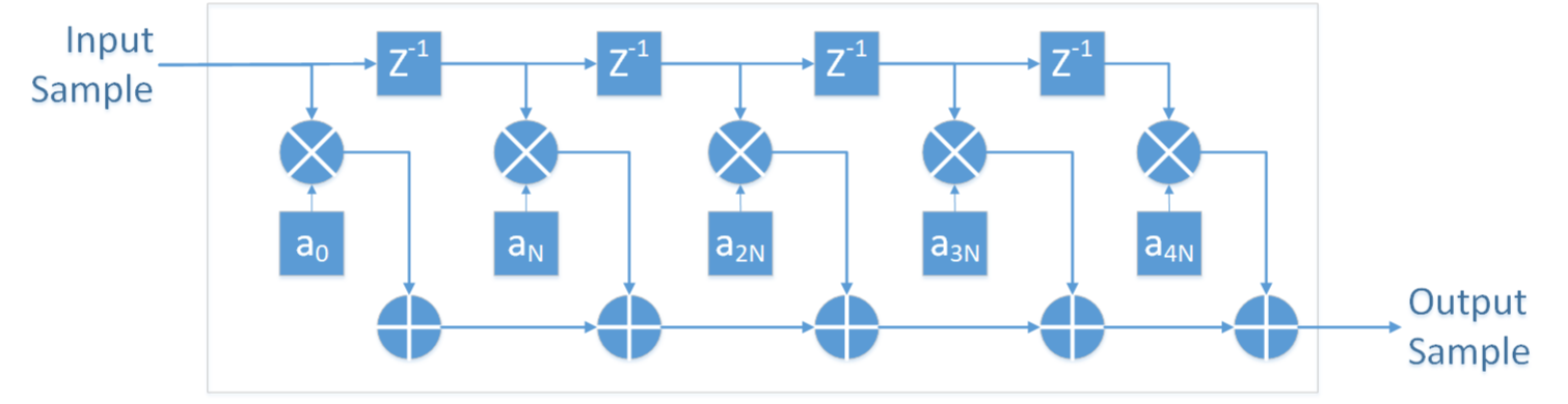
Figure 470: Individual Branch Structure
The FIR taps for branches are stepped, so if \(N\) is the interpolation factor, branch zero would be \(a(0)\), \(a(N)\), \(a(2N)\), \(a(3N)\)…, branch one would be \(a(1)\), \(a(N+1)\), \(a(2N+1)\)…, and final branch \(m\) would be \(a(m)\), \(a(N + m)\), \(a(2N + m)\)… The input samples are pushed through each branch, with a sample delay between each tap-multiplier stage.
Since the FIR structure uses a single multiplier and accumulator design, the input sample rate must be low enough that the FPGA clock is running greater than \(\texttt{sample rate} \times \texttt{number branches} \times \texttt{taps per branch}\). For example, a 100 MHz FPGA clock can handle a 32-branch interpolator with 3 taps per branch and a input sample rate of 1 Msps.
Design
This primitive is a polyphase implementation of an interpolator. This provides the ability for integer interpolation with the actual FIR filtering being performed on lower sampling rates.
This interpolation filter can be used either with a single up-sampled branch selected (sample phase correction), or with all branches being rotated through (interpolating).
The FIR is designed to process signed data, and is capable of output rounding through either truncation (rounding to zero), half up (rounding up), or convergent (rounding to even).
Implementation
The structure of the primitive is shown in the following figure, with descriptions for the main blocks below.
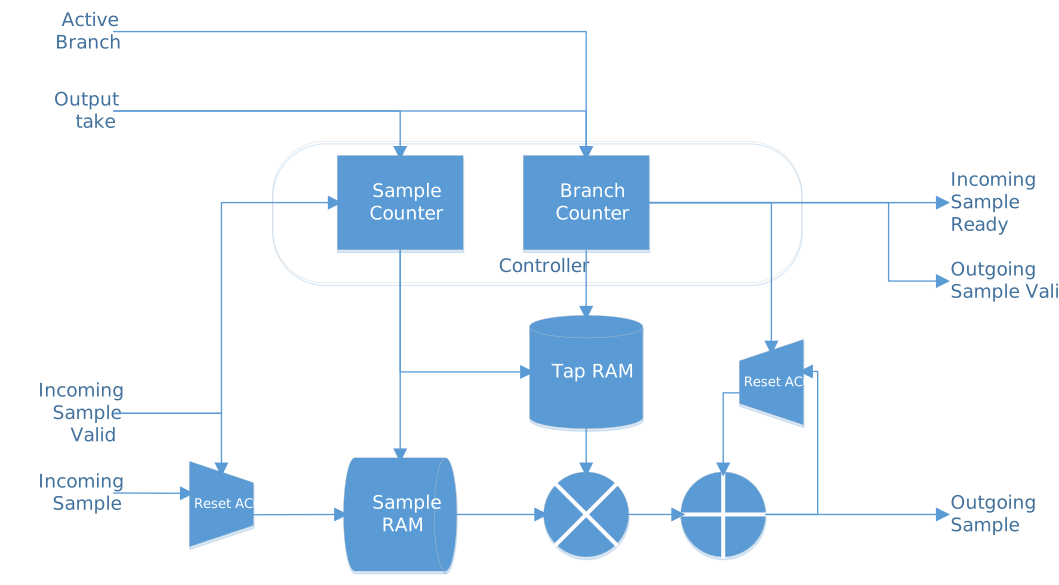
Figure 471: Primitive Structure
The flow of data is controlled by the sample valid being asserted. This in turn causes the incoming sample ready line to drop until the branch calculation is completed. In addition, to aid integration into systems requiring back-pressure, there is an output valid (output) and an output take (input), that provide a FIFO style sample handshake on the output.
The primitive is designed in a resource constrained, burst processing fashion. Therefore it is required that the incoming sample rate is sufficiently lower than the FPGA clock speed.
As stated within the design, the primitive can either produce an output for a single branch (i.e. single input sample = single output sample), or run through all branches (i.e. single input sample = N output samples, where N is the interpolation rate). Which mode is selected is through the generic single_branch_g.
Single Branch Mode
When running in single branch mode (single_branch_g set to true) the FIR interpolator allows the selection of a single branch. Changing of the branch is registered internally on either the assertion of run_single_in or input_valid_in.
run_single_incauses a second calculation without any change to the sample ram.
input_valid_incauses the sample ram to be updated to include the newest sample, and then triggers a calculation.
The sample counter steps the sample ram and the tap ram such that the multiplier sees a new value every clock cycle. Once the requisite number of samples have been processed (defined by num_taps_in) the output of the accumulator is registered, and any rounding calculations performed, before asserting the output_valid_out line. When both output_valid_out and output_ready_in are asserted, the sample is considered to have been read and the process returns to it’s idle state.
Interpolator mode
When running in interpolator mode (single_branch_g set to false) the interpolator generates the output for all branches. In this mode the new samples are only generated on assertion of input_valid_in.
Main State Machine
The following high-level state flow is followed:
idle
Reset the accumulator to 0
input_valid_inandinput_ready_outasserted:
Add sample into the next location within input RAM
Set Tap RAM to index 0
Change state to sample_ram_delay
Clear
input_ready_out
run_single_inasserted:
Set Tap RAM to index 0
Change state to accumulate
Clear
input_ready_out
flush_inasserted:
Change state to flush
Clear
input_ready_out
sample_ram_delay
Change state to accumulate
Used to cater for pipeline delay of RAMs
accumulate
Calculate the value (\(\texttt{input_sample}[n] \times \texttt{tap}[n]\)) and add value into the accumulator
Update \(n\) to the next sample/tap
If reached \(n\) =
num_taps_in
Register accumulator value
Change to state round
round
Apply rounding as set by
rounding_mode_g, which instantiates the relevant primitive
output_valid_outis asserted and the output is available on theoutput_data_outline
Asserting
output_ready_inclearsoutput_valid_outIf
single_branch_gistrue
Change state to idle
If
single_branch_gisfalse
Increment branch counter
If reached
branch_in=interpolation_factor
Change state to idle
else
Change state to accumulate
flush
Cycle through the sample RAM, setting all values to 0
Change state to idle
Setting Tap Data
The Tap RAM is a 2 dimension RAM, (num_taps_in x interpolation_factor), that holds the coefficients. The coefficients are calculated from the total number of taps across all branches, and the desired filter shape. These taps are then split on a modulo offset onto each branch as shown below (with a x4 interpolation).
Generated Tap Index |
0 |
1 |
2 |
3 |
4 |
5 |
6 |
|
0 |
1 |
2 |
3 |
0 |
1 |
2 |
|
0 |
0 |
0 |
0 |
1 |
1 |
1 |
It is anticipated that num_taps_in and interpolation_factor will be set at initialisation and remain static during run time. These two values are used to drive the limits of the actual ram depths used for the Tap RAM.
Rounding Types
Currently the following rounding types, set at build time, are available within this primitive:
Truncate
Half Up - with saturation enabled
Convergent (Half Even) - with saturation enabled
Interface
Generics
complex_data_g(boolean): Whether complex data or real only data is processed.
single_branch_g(boolean): Sets single branch or full interpolation mode.
data_width_g(positive): Width of the tap, data input and output signals
max_num_taps_g(positive) Maximum number of taps possible to set.
rounding_mode_g(string) Sets the output rounding mode
Ports
clk(std_logic), in: Data and control clock.
reset(std_logic), in: Synchronous active high reset.
data_reset(std_logic), in: Synchronous active high data path reset.
enable(std_logic), in: Enable / disable processing of data.
num_taps_in(unsigned), in: Actual number of taps to use per branch (up tomax_num_taps_g).
interpolation_factor(unsigned), in: Actual number of interpolation branches to use (up tomax_num_taps_g).
run_single_in(std_logic), in: Trigger a single calculation with the current value set and data.
branch_in(unsigned), in: Interpolation branch to use/set taps for (used only whensingle_branch_gis asserted).
tap_data_in(signed), in: Value to insert into Tap RAM in the position located through branch.
tap_addr_in(unsigned), in: Address to inserttap_data_invalue into Tap RAM (used for sample offset, whilebranch_inis used for branch offset).
tap_valid_in(std_logic), in: Marks new Tap RAM value is available.
tap_ready_out(std_logic), out: Asserted when the Tap RAM is capable of accepting data (i.e. no active data processing).
input_data_i_in(signed), in: Input real sample data to be processed.
input_data_q_in(signed), in: Input imaginary sample data to be processed (Only used whencomplex_data_gistrue).
input_valid_in(std_logic), in: Marks the incoming sample as valid.
input_last_in(std_logic), in: Marks the last incoming sample (qualified byinput_valid_in).
input_ready_out(std_logic), out: Asserted when the primitive is capable of taking a new input sample.
output_data_i_out(signed), out: Output real sample data processed by the primitive.
output_data_q_out(signed), out: Output imaginary sample data processed by the primitive (Only used whencomplex_data_gistrue).
output_valid_out(std_logic), out: Asserted when a output sample is available and cleared when bothoutput_ready_inand this line are asserted.
output_last_out(std_logic), out: Asserted when the output sample related to the sample wheninput_last_inwas asserted (qualified byoutput_valid_out).
output_ready_in(std_logic), in: Used to mark the receiving process is capable of taking the sample.
Dependencies
The dependencies to other elements in OpenCPI are:
There is also a dependency on:
ieee.std_logic_1164
ieee.numeric_std
ieee.math_real
Limitations
The FIR implementation uses a multiply-accumulate design that limits the number of multipliers used to one for improved resource efficiency, however, this does require a greater number FPGA clock cycles between input samples for processing.