Polyphase Decimator (polyphase_decimator)
Polyphase FIR decimator primitive.
Introduction
A Polyphase FIR decimator, is a sample decimator, which instead of filtering at the higher rate, and then keeping only every Nth sample, the signal is first down-sampled (selecting every Nth sample), and then a subset of the filter taps are used in a multiply accumulate. As a result the FIR is now calculating at the lower sampling rate. This is shown in Figure 467:.
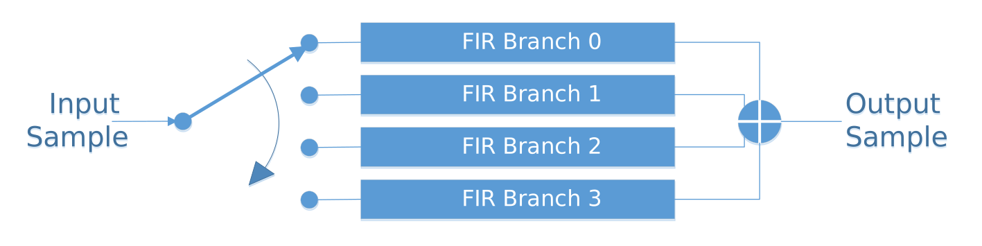
Figure 467: Block diagram of polyphase decimation branching of finite impulse response (FIR) filters
Once all the branches have been stepped through (i.e. returned to branch 0) the output of the branches are summed, and this value is the decimated output.
The end FIR has the structure shown below, where \(Z^{-1}\) is the original pre-decimated sample rate, showing the stepping through the sample and tap RAM FIFO’s followed by the accumulation of the result. This implementation only uses a subset of filter taps for each input sample, therefore allowing a slower clock rate (or less resources) to be used for the equivalent decimation rate.
Design
This primitive implements a polyphase implementation of an decimator. This provides the ability to perform integer decimation with the FIR filtering occurring on the low sample rate side.
The FIR is designed to work upon signed data. Since internally the multipliers are at least twice as wide as the input width, the primitive’s output is reduced down to the input width, and as such offers output rounding through either truncation (rounding to zero), half-up or convergent (rounding to even).
In order to allow fast sample processing, the design is pipelined.
Implementation
The implementation makes use of multiple multiply-accumulate blocks, running in parallel. The basic structure of this is shown in Figure 468:.
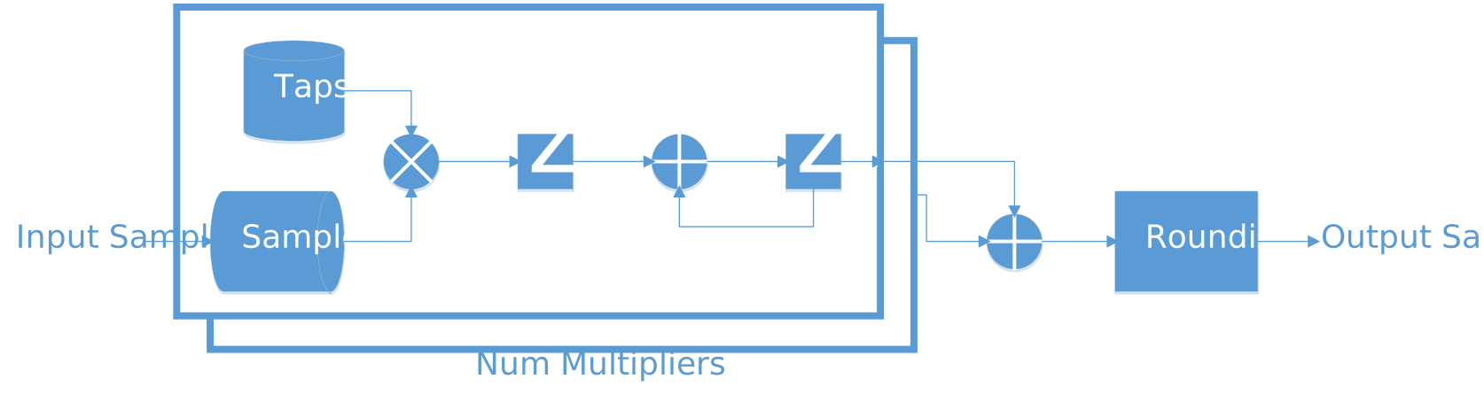
Figure 468: Block diagram of multiplier structure within the polyphase decimator
The input samples are only sent to the multiplier processing that branch. Note that while a single multiplier is shown, if the input is complex, then there are 2 multipliers running together (with the same real tap, but with _i and _q sample data).
This structure can handle multiple branches on a single multiplier, this is achieved by the taps being interleaved between the relevant branches. For example, if there were 4 multipliers the following setups would be used.
Decimation Factor = 2, Taps per branch=3
Multiplier 0: A0 A2 A4
Multiplier 1: B1 B3 B5
Multiplier 2:  0  0  0
Multiplier 3:  0  0  0
Decimation Factor = 6, Taps per branch=3
Multiplier 0: A0 E4 A6 E10 A12 E16
Multiplier 1: B1 F5 B7 F11 B13 F17
Multiplier 2: C2  0 C8   0 C14   0
Multiplier 3: D3  0 D9   0 D15   0
Note that in order to prevent the need to share taps or sample data between the multipliers, some multipliers might be adding zeros, in order to allow alignment of the active samples in the pipeline.
The flow of data is controlled by input_valid_in and enable being asserted together. This will lead to a sample being added to the sample RAM FIFO. Once the decimation_factor number of samples have been consumed, a decimation will commence. If the combination of decimation factor, number of taps per branch and number of multipliers used mean that the number of clock cycles needed to process the decimation is greater than the decimation factor, then the input_ready_out line will drop, Until the number of clock cycles required are less than number of input samples.
The optional input_last and output_last flags are provided, as the latency of data through this primitive otherwise requires a computationally difficult calculation.
Setting Tap Data
The Tap RAM is internally split between the different multipliers present within this primitive, in order to handle the cases where only a fraction of the multipliers are used. the tap RAM has additional zeros entered internally.
In order for this zero insertion to work correctly, the tap array always has to be entered from tap_addr = 0, up-to the desired number of taps.
Tap Address |
FIR Branch |
Tap Position on Branch |
|---|---|---|
0 |
0 |
0 |
1 |
1 |
0 |
2 |
2 |
0 |
3 |
3 |
0 |
4 |
0 |
1 |
5 |
1 |
1 |
6 |
2 |
1 |
7 |
3 |
1 |
The signals num_taps and num_branches should be set at system initialisation (i.e. initial parameters), and then remain static for a given runtime. These two values are used to drive the limits of the actual RAM depths used for the Tap RAM.
Rounding Types
Currently the following rounding types are expected to be available within this primitive:
Truncate
Half_up
Convergent rounding (Half Even)
An assertion monitors this generic to ensure only valid values are allowed. (A generate set should also mean that this is a compile time setting, and should be transparent to the end implementation)
Interface
Generics
data_width_g(positive): Width of the tap, data input and output signals.
max_decimation_g(positive): Maximum number of decimation branches which can be used at runtime.
max_taps_per_branch_g(positive): Maximum number of taps per branch which can be used.
max_taps_g(positive): Maximum number of taps across all branches which can be used.
num_multipliers_g(positive): Number of multipliers to use within primitive (Note the actual number is double this if the data is complex.
data_complex_g(boolean): Defines whether the input data is complex or real only.
rounding_mode_g(string): Defines the rounding mode to use (implements the matching primitive).
Ports
clk(std_logic), in: Clock. Inputs and outputs registered on rising edge.
rst(std_logic), in: Reset. Active high, synchronous with rising edge of clock.
enable(std_logic), in: Clock enable for module. Module is enabled whenenis high.
decimation_in(unsigned), in: Actual number of decimation branches to use (up-tomax_num_branches_g)
num_taps_in(unsigned), in: Total number of taps across all branches
num_taps_per_branch(unsigned), in: Actual number of taps to use per branch (up-tomax_taps_per_branch_g)
decimation_valid(std_logic), out: Asserted when a decimation run occurs
tap_data_in(signed), in: Value to insert into Tap RAM in the position located through branch
tap_addr_in(unsigned), in: Address to insert value in tap_data into Tap RAM (used for sample offset, while branch is used for branch offset)
tap_valid_in(std_logic), in: Tested along with tap_ready to know when Tap RAM value has been updated
tap_ready_out(std_logic), out: Asserted when the Tap RAM is capable of accepting changes (i.e. no active data processing)
input_data_i(signed), in: Real/in-phase input sample data to be processed
input_data_q(signed), in: Imaginary input sample data to be processed
input_valid_in(std_logic), in: Marks the incoming sample as valid
input_last_in(std_logic), in: Marks the last sample of a message
input_ready_out(std_logic), out: Asserted when the primitive is capable of taking a new input sample
output_data_i(signed), out: Real/in-phase output sample data processed by the primitive
output_data_q(signed), out: Imaginary output sample data processed by the primitive
output_valid_out(std_logic), out: Asserted when a sample is available to be read, De-asserts when both output_take and this line are asserted
output_last_out(std_logic), out: Asserted along the last sample (sample entered when the input_last_in was asserted)
output_ready_in(std_logic), in: Used to mark the receiving process is capable of taking the sample.
Dependencies
The dependencies to other elements in OpenCPI are:
There is also a dependency on:
ieee.std_logic_1164
ieee.numeric_std
ieee.math_real
Limitations
The tap array must be entered sequentially from address 0, as opposed to allowing random access.